
The need to illustrate recent speaking engagements, has necessitated the revisiting a virtual model of the Roman timber rampart based on foundations found at Shields Road, Byker, which a real place in Newcastle. [1] In addition, live reaction to my work, provides an opportunity to reconsider and improve its subsequent presentation, and thus every question, comment or observation is important.
Since this particular technological approach, and in particular the underlying reverse engineering, has proved too advanced for a parochial academia, it is worth restating the fundamental methodical differences between CAD modelling and visualisation of the past.
The use of engineering in the understanding of structures can produce models with varying degrees of certainty and spatial accuracy, but what it cannot really do is tell you what the past looked like. While the artist’s reconstruction has become the de facto money shot of archaeotainment staples such as Time Team, and even on the front of serious archaeological reports, a picture is worth a thousand peer reviewed words, ultimately, there is no inherent entitlement or legitimacy to a visual culture of the past.

Above. Trajan’s Column;
contemporary representations [enhanced] of timber ramparts and structures built
by the Roman army during the Dacian War, although stylised, they are clearly constructed with horizontal timbers.
In essence we are trying to understand how this structure worked, not necessarily how it looked. So in addition to a consideration of how such a rampart might be put together, the use of 3D modelling in archaeological analysis will also be discussed in terms of methodology, application, and pitfalls
Reverse engineering ramparts
Reverse engineering ramparts

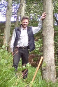
Previous Work on this type of structure has been well documented on this site; my initial modelling is always on paper in the form of a technical drawing, although in this case, I also built a scale models using match wood. Since they are time consuming, I only build 3d computer models of structures to test and demonstrate ideas, once I have a clear objective in mind.
This post is illustrated with screen “snapshot” of a 3d computer model in SketchUp, the quality of which is related to my computer's screen resolution. I could also output moving images from the model, such as a walk through or a panning view.
Quite unlike modelling a building, the key conceptual idea is that it the spaces between the posts that give the structure its utility. The robbed post pits at Shields Road suggest a foundation of posts placed in pairs, around which a rampart constructed from horizontal timbers placed at 0˚/ 90˚ to the line of the structure with others placed at 60˚. This would produce a very strong and credible structure with a wide fighting platform. The plan of this structure is entirely consistent with scale of timber ram parts frequently mentioned in the writings of Caesar.
“He orders him
to fortify a camp with a rampart twelve feet in height, and a trench eighteen
feet in breadth”.
Caes. Gal. 1.6[2]
 Computer modelling, while it has become much easier, is still labour intensive, so it is important to define the objectives and scope of your project at the beginning. This helps determine the structure of your model in terms of components and layer; each baulk of timber is a component, and can belong to a layer, a group of components that can be visually turned off and on.
In most cases the model is based on an archaeological plan, which is imported into the model as an image and scaled.[left]
Since we can be absolutely certain that old buildings were not laid out in metres, I always work in feet and inches, as this is usually how ancient structures in Western Europe were conceived and built.
In theory, the model is as accurate as the information transferred from the original plan [and section] data; if necessary you can work to an accuracy of fractions of an inch, way beyond the tolerances of most archaeological planning.

[Above] Scaled posts are
placed on the ground plan in their original position; these are the fixed
points around which the model is constructed.

[Above] In this case, a
reconstructed ground level with ditch and spoil mounds is developed from the
archaeological plan to provide a visual context for the model.

[Above] A set of standard components are usually
prepared in advance; there are roughly 600 timber baulks in the model with 13
variations, ranging in frequency from 3 to 182.
Each cloned component is then individually positioned in the model, in this case, fitted into the spaces between the posts.
The original layout of the posts lends itself to particular methods of construction which are demonstrated in different parts of the model.

[Above] A front view of the model showing construction detail; the base is constructed using pseudo-randomised forward pointing angled baulks. The section above is built using 0˚ & 90˚ baulks in a regular pattern, alternating in direction to compensate for taper.

Above: A detail showing how baulks projecting at an angle obscure, lock, and protect the posts at the front of the structure, [the most obvious point of weaknesses in the design].
The issue of
what happens at the top of the posts i.e. are they jointed or nailed together
in some way, which would be desirable, is not addressed. This represents
another set of possibilities which could be modelled, but it’s not an issue that
be easily or satisfactorily resolved.
Getting it wrong....

 Modern systems are comparatively easy and quick to use, or equally abuse; a casual click or an inadvertent flick of the mouse can create components and pitch them into another part of the model. In positioning of components you have to attend to the fit at both ends which are often not both in view at the same time. [Left] A badly constructed section with components overlapping and intersecting inappropriately. It is usually best to "lock" components in place one they are satisfactorily placed, and to be constantly vigilant about checking fit between components, much of which is "hidden" inside the structure. [Right] Did you spot the deliberate mistake above? The pencil-like tips of some of the baulks are missing; due to a error, they are part of a different layer which was not visible.
[Above]. A typical error, with the two baulks in the centre occupying almost the same space and visually merging.
In most systems there is a practical limit to amount of information that can be displayed or rendered. While it is possible to store vast amounts of image data, to process and display a high level of detail is more complex especially if the image is ‘moving’.

[Above] a plan view showing a section built from regularly placed [0˚/ 90˚] baulks over a layer of regular 15' bracing 60˚baulks.

[Above]; Art for art sake; potentially, each component can be unique; an amount of time was invested in creating some slightly more realistic timber baulks, principally, to make the point that this was unnecessary and a waste of time in this context.
The slightly more realistic baulks with stubs and scars of side branches represents 10 or 20 more data to be displayed and manipulated.
They are bespoke hand crafted “digital art”, and extremely time consuming to produce, but apart from adding to artistic realism of the image, they contribute nothing to technical aspect of the model. Real timber baulks/ logs in this context would be effectively random within some complex parameters to the extent that is impractical to reproduce this in a model. Building in a computer is thus different from building something out of real wood that might be attempted by an experimental archaeologist.

[Above] a section of typical "box rampart" structure built with some more "realistic" individualised baulks.
Each component can be unique, however, while it might be “visually” more realistic and could to some extent reproduce the practicalities of construction, using pseudo–random components is no more “real” than using standard components, it only appears so.
At some point in modelling a structure such as this you reach a point of diminishing returns; enough has been done to demonstrate the basic thesis, further speculation adds nothing to our understanding of this structure as a rampart.

[Above], A plan view the use of 15' baulks at 60˚ in bracing the structure near the top.
The model has successfully served to demonstrate how the archaeological plan can be projected and superstructure modelled. All the basic constructional techniques which appeared inherent in the ground plan have been successfully modelled to scale. It may appear unfinished, but this is a 3 dimensional cutaway diagram, archaeologically accurate in two dimensions and proportionate in a third.
[Above] A platform on top of the rampart with a wickerwork front [battlement] as described by Caesar [2]; this component is highly detailed and represents a significant amount of information, probably equivalent to several hundred of cloned baulks forming the majority of model structure.

While “pictures” and “diagrams” both convey information, the former tends to interact on a more emotional level, while the latter is aimed at comprehension and rational engagement.
Each individual model, like any diagrammatic representation, has to be understood on its own terms and visual conventions; your house may have started off flat with a bluish tinge, but that is not how it ended up. You may buy a new build house based on a picture, and perhaps a plan, but the builder required a set of diagrams, to convey the precise technical information required.
While such observations are already out of date, the ability to build virtual models in photo-realistic detail threatens to blur this important distinction. For the house builder this is a sales tool which can visualise the house with red carpets and green walls, or vice versa. However, for the archaeologist a diagram should express real data, as distinct from a picture, which however artistic or realistic is a work of the imagination.
Computer models are clever diagrams.
This explains why it is this websites somewhat radical policy to add anachronistic spoilers to images, just in case the viewer imagines they are dealing with an artistic representation, a picture of the past - one of those fictionalised conceptions which is added to enhance and give weight to a peer reviewed text.
Archaeology is only credible if we are able to embrace the idea of doubt and close our eyes to the beguiling simplicity of a visual past.

SketchUp Roman rampart model seen in plan.
Sources
[1] Grey literature: Shields Road, Newcastle, Phase 2b, archaeological excavation. TWM archaeology 10/2006
See also; Bidwell, Paul T.; Watson, Moira. 1989 'A Trial Excavation on Hadrian's Wall at Buddle Street, Wallsend'. Archaeologia Aeliana, 5th ser., 17 (1989), 21-28.
And
T. Frain, J. McKelvey & P. Bidwell 2005 Excavations and watching brief along the berm of Hadrian’s Wall at Throckley, Newcastle upon Tyne, in 2001-2002. Arbeia J, And Bidwell, P T, 2005 'The system of obstacles on Hadrian's Wall; their extent, date and purpose', Arbeia J, 8, 53-76. http://www.arbeiasociety.org.uk/journal.htm
Grey literature; Throckley, Newcastle upon Tyne, archaeological excavation and watching brief. TWM Archaeology 12/2003
[2] Caius Julius Caesar "De Bello Gallico" and Other Commentaries English translation by W. A. MacDevitt, introduction by Thomas De Quincey (1915) http://www.gutenberg.org/etext/10657


9 comments:
hi geoff.
i posted an article several years ago on my blog and also more recently with Graham Hancock in which i describe the methodology that can be used to build the Great pyramid while constrained by bronze age technology and on time and on budget.
It struck me that it would be possible to work with you to produce proper illustrations of the methodology. The critical breakthrough came from left field and begs for illustration.
bob (arclein@yahoo.com)
Hi Bob, thanks for the comment; I am not up to speed with pyramids - internal ramp looked logical.
I am always happy to help with illustrations, within my fairly limited range.
The internal system and the long external ramp run into serious and fatal issues as the scale in increased. both where used for much smaller structures and their limits were the well known.
The great pyramid was build one level at a time using the outer shell as a retaining wall for a water filled pond in which flat boats carrying blocks could be positioned and then themselves removed by sliding down the side of the pyramid.
Thus is becomes necessary to build a multi story lock system using reinforced timbers on a post and beam system. Such a system when fully loaded can rapidly deliver blocks to complete a full level inside a couple of days even for the core and likely longer in order to properly position the new level of the outer shell.
With this system the actual issue is compressible beam strength and wood splitting. I was able to overcome both and identified the wood supply as well.
I have thought out the details quite thoroughly but text can never come close to convincing anyone else.
An aside. the water pond provides a natural leveling system for the pyramid and makes the observed precision easy.
That's interesting, but I wonder why your reconstruction is more elaborate than the images from Trajan's Column, which seem to show solid layers alternating at right angles.
What would be the advantage of either version over the apparently more economical vertical 'Wild West' fort type of wall? If it was meant to last a long time and be less of a fire risk, why would they not have filled in the spaces with earth?
Ho OR; Very interesting point; the Roman carving is an "illustration" - something of an ideal, and a bit cartoon-ish with all the pieces of wood the same size. Also, I am building a model based on the position of the posts at this particular site which is attempting to explain how the structure could work.
In this and many other military contexts the structure was temporary, built with freshly cut wood which is very hard to burn.
The spoil at Hadrian's Wall is thrown to the North, which effectively creates a deeper more dangerous ditch, which is harder to escape from. This was a temporary structure so filling it with soil would be counter-productive.
In Caesar's accounts it is clear that ramparts and ditches are built consecutively - that order.
Hi Bob;
Very interesting idea; good illustration would be useful.
Wood supply is a problem in Egypt, but Lebanon was a well documented source of structural timber, presumably with other areas of the Mediterranean.
However, as a structural archaeologist there are issues, which generally apply in reverse engineering.
Technology is evolutionary - dependant on what is been tried and tested before; any "solution" to the great pyramid must be relevant the long period of evolution of this type of structure, which include mud brick examples, and others not well situated for water sources.
I would expect to see specific adaption in the design to accommodate water, for example to restrain the lateral forces.
Logistically, using large volumes of water at height increases significantly the mass to be raised, even assuming the same water is retained.
Using shadoof / shaduf to raise the water is fairly slow in terms of flow rate.
In general terms, I am looking for the evidence first, and the theory second, and in this case I can't think of any supporting evidence for the presence of large volumes of water, or adaption of design.
However, this is not to say it does not work as a theory.
I have the same problem with prehistoric / ancient buildings
" .. but I would not start from here" as the punchline of an old Irish joke runs always seems appropriate; another way of looking at this issue is that railways are development of prehistoric carts and wagons, resulting in railways are than are [unnecessarily] narrow.
Apart from its size, the great pyramid does not seem more unique than its predecessors, so I am looking for a solution common to all or at least an evolution of such.
Thanks Geoff. What do the military re-enactment people think of this? Have they tried any experiments in building like this, and attacking/defending such structures. Is it easy to erect or move? Would they have filled it in with spiky branches? Is the potential 'see through' problem for defenders countered by the bank hiding the ditch and the ground level up to man height?
Interesting observations; I have discussed it with Parties wishing to build Historic recreation; the stumbling block are a] the amount/ cost of wood required, b] the need to conform to existing ideas about piles of soil with a fence at the top, c] a prevailing view is that anything archaeological should be simplistic and built by students.
It is fairly simple to make non-see-through at the those heights that matter.
It is quite clear that the spoil goes on the attackers side, but the defenders advantage of height more than compensate for this; it is also felt that loose soil and a slope disadvantage the attacker. There is a structure called a Punic ditch, which is markedly steeper on the outer face; it is the same idea of making it difficult to escape.
If your attack fails you will have to turn your back and run away - this is when you are most vulnerable - and slowing you down makes you vulnerable for longer.
Nice blog thanks foor posting
Post a Comment