In the last article, we looked at prehistoric architects. However, the reason this is theoretical structural archaeology, is that we have not found any. What archaeologists have recorded are the foundation plans of thousands of prehistoric buildings, along with large amounts of structural evidence we don’t yet understand.
The structural analysis in this article has been superseded by a new article; Understanding the Neolithic Longhouse.
In this article we are going to take serious look at some of the important issues in modelling buildings from archaeological plans.
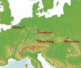 We shall look again at the plans of Neolithic longhouses from Elsloo [1]and Olszanica [2] and see what they tell us about elevations.
Visualising scale
It is easy to take it for granted that as long as a plan has a scale bar, readers will be able to visualise the size of the building. However, if you do not work regularly with plans, there is no reason for this to be true.
Some time ago, Martha drew my attention to this; it is an issue that anyone presenting archaeology must think about. In future I will try to remember put a human scale into drawings where possible.
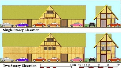
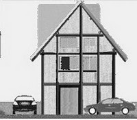
I intend to consider the whole issue of scale in archaeology of the built environment, and how best to visualise it, on another occasion.To make amends, I present two models of the Elsloo 32 longhouse using Ford Mondeos as a scale.[above] Not that I am suggesting this become an international standard for archaeological drawings, but it serves very well to illustrate longhouses, which are best conceived as wide as a double garage. But exactly how tall they were is the much more interesting topic which goes to the heart of this article.
Secret life of archaeological plans
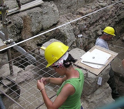
Using a planning frame on an excavation in Rome [3]
From the somewhat myopic perspective of TSA, the key data set recovered from the site is the plan of the features; the rest of it is largely people's rubbish!
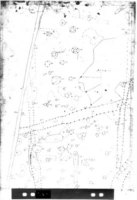 This site, and most books on prehistory, have plans of archaeological features, and before we get onto the issue of how to read them, I want to give you a rough idea of where they come from, based on my own experience, using examples from Orsett in Essex.[4] Equipment and practice has varied over the last 100 years, and is now changing radically with the introduction new technology. The basic idea is that a grid of fixed pegs is laid out across the archaeology site, breaking the site into imaginary squares. This is then used to fix the position of a planning frame laid on the surface. The planner uses a grid of fine elastic stretched across the frame to scale the features on the ground to the graph paper backing of a hand-held drawing board.The plan is drawn in pencil on transparent drafting film, using a set of standard conventions, which usually include OD height information on important surfaces. It is annotated with feature numbers, cross-referencing the site's other recording systems.
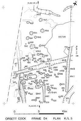 General archaeological site plans would probably be recorded at a scale of 1:20, and a large posthole ends up the size of a bottle top [above with inverted plan chest hanger]. Sections and more interesting features, such as graves, are usually recorded in more detail and at a larger scale. In Colchester, for example, Roman mosaic floors were recorded 1:1 and later hand coloured. In post-excavation these plans will be copied, traced, or have the pencil inked in, before being reduced to a manageable size.[left] Accurate and true reduction of these plans is not necessarily a straightforward process, depending on the technology available.Needless to say, problems can arise when joining the individual plans together, since even a modest site may have several dozen such plans to join together and overlay, often drawn in different seasons of excavation. As a result, the process of combining individual sheets to produce a master site plan is often quite tricky.[below]The scale of these master plans will depend on the size of the site -- it has to fit on a drawing board. A reasonably sized excavation might end up at 1:200 for example.
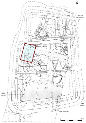 These drawings will undergo a further round of reproduction and reduction before appearing in print.
 It is a professional courtesy to assume archaeological plans are accurate, but we should be aware that mistakes are made, and that the plan of an ancient building has been on its own individual optical and reproductive journey before it reaches us.Working with evidenceIt used to be the case that only through the physical act of drawing the plans and elevations that the architect, or even an archaeologist, can define a structure and see that it ‘works’. CAD has changed this. I started using it for archaeology 20 years ago, when nobody was interested, so I am no Ludite, and computers are fabulous boon to illustration in archaeology.
However, I would seriously recommend that you try and work on paper, at least at first. A drawing board is ideal, and most importantly, dividers. They are simply the best invention ever for quickly comparing or transferring measurements. You should be able use a setsquare, protractor, and compasses well enough to draw parallel lines and right angles. Tracing paper is still very useful, as are coloured pens and crayons.
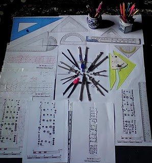
Get used to working at the same scale. I find 1:100 convenient for all but the largest structures. I don’t recommend you work in metric, since it is the one measuring system I think we can discount in this context. You may wish to make appropriate scale rules. Units traditional to the area are a good starting point, but it is far more important to think in terms of proportion.
While archaeologists are in some sense reverse-surveying the foundations of buildings, the ‘plan’ is anachronistic in this context, since however the building was conceived, it certainly was not on paper. One may imagine an ancient world of ratios, rules of thumb, pegs, and plum bobs, rods, and string, and one day some this culture may become apparent from our plans. I try to take note of the obvious internal geometry of structures. However, this, and the issue of metrics, is best tackled once the structure has been more firmly understood.In essence, the problem is in knowing which dimensions in the plan were significant to the builder. Important dimensions like the length of rafter can’t really be measured directly from the ground plan. Also, if you are serious about metrics, you really ought to work with the original plans.One important part of the evidence, posthole depth, is not always considered a priority by excavators with limited resources, and is often not available. This is the case with Olszanica, and this limits in the degree of confidence we can model this building. However, since this is not unusual, it provides an excellent case study for working in plan only.
Theoretical treesTimber is grown for specific uses, so given sufficient continuity of purpose, and within the potential of species and growing conditions, woodland can produce the timber the builder needs to produce, maintain, and renew the built environment as required.
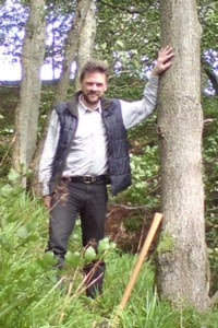
 What lengths a builder could reliably obtain is a central question; in an ideal world we will be able to read this from the plan. As a guideline for a hardwood like oak ‘in the round’ [left],I would say timbers 20’ – 30’ are normal, 30’- 40’ are long, and 40’– 50’ are exceptional. Timbers over 50’, I expect, would have to be split from the trunk of a larger tree, or use a different species. Splitting the larger trees can provide a range of timber pieces such as boards, and square sections.This is all very general, but the issue is not the top height of the tree, but finding one that is straight with no branches over the required length.
In the theoretical model of Elsloo 32 I wanted to illustrate the problems of building with tapering timber, and how this might influence the plan.[5]
One of the reasons I chose Olszanica LH6 was because of its size, or more specifically its length. To make a building over 120' long, the main components must be made of several tree lengths. So for Olszanica I might be looking at three 40’ timbers, or perhaps four 30' ones.
Remember these components have a thick end and a thin end, so try to envisage this in all dimensions, and think about how you might go about compensating for this in the way you would layout and assemble the building. Don’t be surprised to see small postholes at one end of some conjectured timber and larger ones at the other.
The beginning and the end
 The LBK longhouses at Elsloo and Olszanica discussed in recent articles represent the beginnings of the timber building in northern Europe. More than 6500 years later, buildings were still built of the same earth, with wood and thatch, perhaps even grown in the same woods and fields established by these first agricultural pioneers.
In the intervening millennia, building technology had moved on with the introduction new metal tools, allowing more complex components and joints. New assembly techniques, and the refinement of ideas about loading, created more efficient buildings with larger open spaces, less obviously encumbered with supporting timbers. A La Tene example from Manching, Bavaria, illustrates this [6], although it may have a different function and internal arrangements from the Olszanica longhouse. The arcade is no longer evident, although the ridge piece is still supported.
I take it as read that LBK builders could create all the basic features of vernacular medieval timber farmhouses, [apart from chimneys]. So roofs, walls, floors, doors, windows, and stairs have been ‘invented’ by this time, and will be used as required.[7]While some degree of similarity of functions and materials can be presumed, I should point out that my knowledge of medieval buildings is in an English context, and quite how, or even if, these buildings are reflected in their local vernacular tradition, I am not in a position to judge. In a medieval building, the wall foundation was probably some form of solid plinth, of stone at best, with horizontal timber sill beams set on it. Walls were now based on vertical studs and posts jointed into this wooden sill. Larger spaces may have freestanding posts, but prehistoric-style earth-fast posts become increasingly rare in the medieval period, certainly at the quality end of the market. Also, it is not a good idea to mix different types of foundation in one building.

 This is a good point to allude to an awkward problem for TSA: what to call these conjectural timbers, since it is sometimes difficult to find generic terms for objects with quite distinctive functions. I try to keep it simple, consistent, and use the term ‘plate’ in preference to ‘beam’.
I use the term timber-frame fairly freely; a purist might argue that it refers to particular techniques of construction used in the medieval period that are markedly different from those of the Neolithic. However, these structures still had posts, plates, rafters and purlins; what changed was the way these bits were joined together.
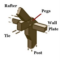 These four basics components could now be now assembled in a single joint. In some ways, building carpentry can be viewed in terms of the evolution of this, and other crucial joints.[8] This makes assembling the building much easier; it can be built in ‘frames’, then erected and linked together, or pre-fabricated roof trusses could be placed on solid walls.Using squared timber of similar section, it is possible to create ‘scarf' joints for joining timber end to end. A Neolithic builder is unlikely to attempt this with two tapering trees. However, just as in the medieval period, if you can make a hole in the timbers to be joined, you can use a peg, also known as a trunnel or treenail, to hold the joint. While jointing is the clever bit, it also involves cutting holes in all the constituent parts, reducing their strength accordingly.Tying it all together
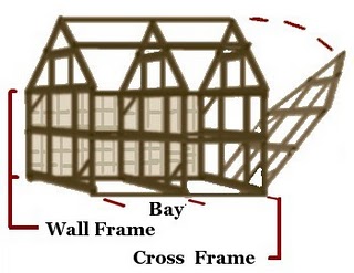
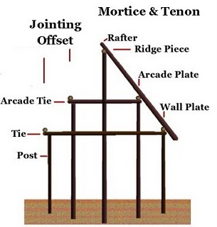
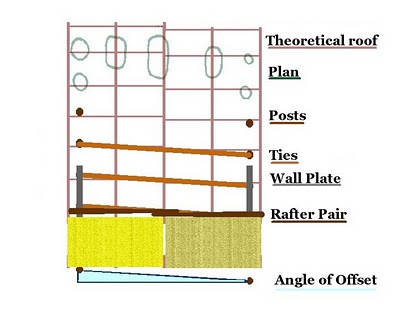 The use of reverse assembly, starting with ties set on pairs of posts, explains much of the ‘irregularity’ in longhouse plans, in particular why the posts in opposite walls don’t quite line up. This was one of the important points I was trying to illustrate with the model of Elsloo 32.The rafter pair straddles the tie, which runs at a slight angle to accommodate this arrangement; this simplifies the jointing, and ensures they are at 90° to the ridge. [above]
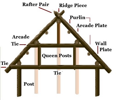 Instead of all four elements fixed in a single joint, medieval style, the rafter joins the wall plate, which joins the tie, which joins the post. The post does not necessarily have to join directly to the wall plate. There are opportunities to joint the rafter to the tie with a tree nail.An introduction to Post TheoryThe abstract theory of how to extrapolate models of wooden structures from archaeological features, I call it Post Theory. [I don’t want to overdo this, but this is a new way of thinking about the evidence, and I can’t avoid having to come up with some new terms.]It is really fairly simple, a bit like bricklaying. There only a limited number ways you can fit the bits together so they work.The only ‘known’, our starting point, is the position of the posts. Their relative height may be inferred from the depth of the postholes, but what happens at the top of the post is where Post Theory takes over. It is not really a set of rules, more a set of considerations, perhaps a protocol, for establishing the structural bona fides of a set of postholes.We will be returning to this topic, but I want to start by looking at the comparatively well-understood form of a LBK longhouse in these terms, since this is very much our baseline for timber architecture in the subsequent millennia.Roof Pitch
Although 45° roof pitches are simple to draw and calculate, I am more comfortable with steep roof pitches; 53° and 6o° are both easy to work with. The benefits to weatherproofing, snow loading, and the utility of the roof space, far outweigh concerns about using more materials, especially in a building of quality. Any complexity in the roof shape will result in valleys, which can become problematic in slacker roof pitches.Concerns have been expressed about wind resistance of a taller roof [9], but if adding 6’/2m to the height of your longhouse ridge is going to threaten its structural stability in windy weather, it rather suggests that the basic design is a non-starter.
AssemblyI know it appears self-evident to say it, but there is an order in which buildings go together. The plan holds clues to this, and it is important to consider what supports the structure as it is being built. There is no reason why some postholes can’t be associated with construction.In timber buildings, the order of assembly is quite significant, with implications for the ground plan. In a normal assembly roof, the tie, now part of a roof truss, sits on top of the wall or wall plate, but in a reversed assembly roof, the tie supports the wall.While this is neat way of explaining why postholes don’t line up, it is also a very useful technique for dealing with timbers that are tapering and not perfectly straight. It is simpler to put up posts in pairs with a tie running between them, and use this to support and level the wall plates, as opposed to lining up a series of posts jointed directly into the later.
In Neolithic buildings, the ridge piece is supported directly and would be one of the first things that was put up, supported on its own a set of posts. This was probably true of the arcade plate, but purlins are another important timber that need supporting. These timbers run length-wise either side of the arcade, supporting the rafters. Purlins, and other timbers, can be supported by posts tenoned into the top of the tie, pairs of which I refer to as queen posts.
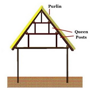 This is an important aspect of Neolithic roof design, which we will return to when we consider ties in more detail below.
Probably you would expect two sets of purlins, probably midway between the arcade and the ridge/wall. This, again, is something to look out for, and account for in a model and its assembly.
Braces
When we model buildings and structures in this way, we are working on the main components evident from the foundations, running along and across the building, but we are aware of the need to brace the structure in all planes to prevent racking [diagonally]. Working in plan, it is sometimes possible to draw attention for opportunities for horizontal bracing timbers.
Post theory and uncertaintyAs we are dealing in something that no longer exists, one of the most important concepts is uncertainty; being aware that we cannot know the position of some things for certain. In a very important sense, we ‘know’ where the post was, since we have the hole dug for it; after that we have to make some assumptions.
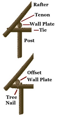 Normally, for basic structural stability, it is assumed that the post will be positioned close to the junction of horizontal timbers running in at least two different directions. The top of the post will narrowed to form a tenon, which passes through a hole, or mortice, in a horizontal timber. If we are dealing with a reverse assembly structure, we may expect the post to support a tie; thus we have pairs of posts with a tie between them, as a basic unit.
Now, at this point we have two possibilities [left], either:
A. The narrow tenon at the top of the post passes through a mortice hole in the wall plate, or
B. The wall plate could be offset from the head of the post and jointed only to the tie.
So there is often a theoretical possibility that the main timber is next to, not directly over, the post.
 While TSA is about good basic geometry in a building, we have to build this uncertainty principle into our thinking, and be aware of a tolerance of about 'a post thickness’ in models, where appropriate.
At the same time, it is important to chase down inaccuracies, as this is usually a clue to some aspect of the structure for which the model does not account.The central point to keep in mind is that being adjacent to something can be just as significant as being in line with it.Joining the dotsAnother important tip in structural analysis is that there is simply no point in having two posts adjacent to each other if they are at the same height. When you see pairs of posts that very close together or share the same hole, it suggests they support horizontals at different heights.We must also be wary of being simplistic about ‘alignments’ of posts. It is normal in buildings to align vertical elements, even if they are at different heights, as is clearly the case of those posts running across a longhouse.The idea that a line of postholes is a 'wall', even marking the 'physical boundary' of a building, can be an over-simplification, as its position is more properly related to that of the roof, and may lie inside or outside the physical wall.
The gable paradox
 In a longhouse with a pitched roof, there may be advantages to having some form of gable on the side [or end] to allow for light and ventilation, as I suggested in the Elsloo 32 model, This is an interesting problem in longhouses, and Olszanica is no exception, in many ways easier to draw than describe. [left]
While the main roof is supported on posts sunk in the ground, the roof of the gable might be supported from the wall plate. To simplify the jointing, the posts supporting the roof from the wall plate might not directly above the posts supporting the wall plate. So perversely, you can find a pattern of posts that are precisely not where you might expect the posts to be, which may be considered significant.Upstairs and downstairsLet's be perfectly clear about this: creating a raised wooden floor is not technically difficult. If one is needed, it can be produced simply, even 7000 years ago. In some contexts such as Neolithic lake villages, they are considered normal.[6] In Northern Europe, people with the choice have shown a marked preference for sleeping, and often living, upstairs. Animals do fine down stairs, and even contribute heat, which rises, to the building.
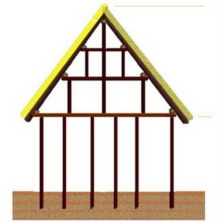
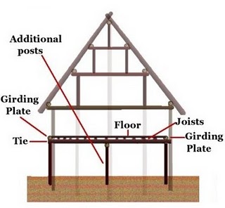 In a bungalow type elevation, only the roof space would be floored, but in taller elevations ties, positioned well below the roof, support joists running along the building carrying the floorboards running across.[left]. The ties support a girding plate, marking the edge of the floor, which can be inside or outside the line of the wall. Additional posts may occur to support the floor bearing ties, perhaps along the centre line of the building.The additional ties at floor level, the floor itself, and the joists and girding plates increase the rigidity of the structure. Most of the timbers in a longhouse are at least 20’/6.0m long, and similar timbers could quite conceivably give rise to a two- or even three-storey elevation if this was required.The relative depth of the postholes, which in some excavated examples do vary accordingly, can be used to gauge the relative heights of ties, and any additional posts supporting them. Posthole depth is not available for Olszanica, so a complex model elevation is not possible.Olszanica bottom to top
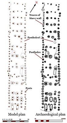
We have already looked at some aspects of this plan.[9] It has a rather vague tripartite structure, with two unusually wide entrances. There are traces of a stave wall at the NW end. The fact that it is mostly missing indicates it had a shallow foundation and was probably not structurally significant.The first step is to map out the posts, reducing the postholes to appropriately sized dots. As most of the structure is unexcavated, some of the features are uncertain, and it is not possible to colour code according to depth.Internal GeometryThe next two steps, establishing the building’s geometry, and establishing its basic structural components, effectively happen together. If only for the ease of presentation, internal geometry is covered first. Initially, as already noted, concern is for general proportions. Don’t worry about metrics, work with the simplest measurements inherent in the plan [using dividers!].

Imposing a fixed grid on an ancient plan may seem odd, but these structures would have to have had sound geometry, or they would have fallen down. This is not to imply the precise geometry used to layout the plan, it is more to draw attention to the underlying regularity in the plan.
We have noted the significance of offsets and things that don’t quite line up, suggesting this is largely a result of creating a regular roof. Another consideration is the placing of braces running diagonally across the structure.
60° Geometry
In general terms, we can view the overall structure in terms of ‘x’, the distance of the ridge to the wall, and in this case, as so often with Neolithic longhouses, the width of the arcade.
So the building is 2x wide. We can view each of the three main section as 4x long, and the whole structure as roughly 12x by 2x.
‘x’ in this building is between 9’ and 10’.
This diagram also shows lines at 60° to the long axis of the building. Many of these link all five lines of posts, and may represent either surveying lines or the potential position of bracing. The northern section is the most regular, particularly the arcade and ridge; however, the far northern end does not work well.Without knowing the structural significance of each post, it is difficult to be sure about bays [the major divisions in the roof]. The north end is supported about every 7–8’. Using that as guide, we can envisage a series of bays that would fit with entrances on the eastern side. This could imply that only every third post was tall enough to support the wall plate.
45° Geometry
This diagram was initially designed to show basic squares in the geometry of the building, which would facilitate the positioning of side-facing gables and other proportional roof features. However, it works surprisingly well as a general description of the layout. Note how in places the posts fit with the grid on each side alternately.
I hope this illustrates, without defining the methodology and geometry any further, that the skill underlying this structure is quite exceptional, and what might first appear somewhat ramshackle, is in fact probably considerably more subtle and sophisticated than our ability to decipher it.
This is architecture.
Roof Structure
Meanwhile, back with the model foundation plan, our initial approach is to find the centre of the roof next; the rest of the structure should be symmetrical with this. In a Neolithic longhouse this is not normally a problem. Start with the most regular bit, which in this case is the northern section, where there are clearly three lines of posts, fairly evenly spaced, so no real problem there. The actual north end of the building is problematic, with only a centre post and no trace of the arcade, so this goes on the snagging list.
 Remembering about the limits on our theoretical timber, quite what happens between the northern and the centre section is not clear. There is an apparent gap in the ridge and the eastern side of the arcade, and I suspect that some form of gable or other variation in the roof form may be indicated here. The two posts on the eastern side opposite the entrance, and the two posts symmetrical with the ridge in the position where purlins might be expected, are also worth noting.
The central section has a well-defined ridge, but the arcade is rather vague in places, with several posts closer than expected to the wall line. The posts are generally more widely spaced, and the roof structure appears slightly offset to the west. Again, there is a rather messy transition to the southern end section.
Assuming that this section, at least in terms of timber, must start at, or just above, the area of the wide door, it is similar to the arrangement on the northern side of the centre section. Perhaps we should view this a five-division building.
The far southern end has the characteristic double postholes. The ridge appears slightly off line to the east, closer to the alignment of northern end. This emphasises the distinctive nature of this part of the building.
Ties and Wall PlateWhile most of the ties are fairly obvious as a pair of posts, the wall plate is altogether sketchier, and its position is determined mostly by the geometry of the building, as best it can be modelled. I have tried to keep it as simple as possible, in places there are some uncertainties, and apparent alternatives, in the positioning of ties, but without all the data, exploring all possibilities is of limited value.
I have highlighted areas on the plan I think are the position of wall plate junctions; how wall plates might ‘join’, or more appropriately overlap, will be discussed on another occasion.

Most ties have an angle of offset [3--4°, but up to 5°] that we might expect in our pitch roof model. Some are at 90°, suggesting that either there is not a pitched roof at these places, or the tie is below the roof and not supporting the wall plate, but a floor. Others pass adjacent to the central and arcade posts, offering the opportunity for jointing to increase the rigidity of the structure.
Two posts on the NE side lie outside the line of the wall, which is difficult to explain if these posts are at roof height. Both wide entrances on the eastern side are marked by the absence of a pair of posts. This prompts the question, as with Elsloo 32, what is the function of the posts opposite the entrances. In the northern example here are two posts opposite the doorway, on the line of the arcade. While these postholes roughly ‘line-up’ with the posts in the western wall, without knowing their relative placement depth, it is difficult to be sure if this is significant.
We have noted the relative over-design of the Neolithic longhouse, but to build a roof with a tie every 3’/1.0m or less is perhaps overkill. It is a 20’ span and, as suggested above, 7’ –8’ might be better, and still conservative by later standards. Given the builder seems so happy to miss out, or misplace, pairs of ties, it is not unreasonable to suggest that we are dealing with ties that are below wall plate height, and therefore probably supporting a floor or floors at an intermediate height.
If we follow the logic of evenly spaced ties, then if every third post is significant, this actually implies two suspended floors, as well as a loft at roof height.
Going upstairs in the Neolithic
In a context like a domestic building, if you have an upstairs, you must expect there to be stairs. Some might argue for a ladder or perhaps a knotted rope, but this would prejudicial to the elderly, infants, and anybody carrying something.
Stairs are vital components, central to the functioning of a multifloored built environment. They are serious load-bearing structures, which are required to remain stable when subject to considerable dynamic loading. At the risk of a circular argument, if you think your building has floors, then see if you can find the stairs.
If it is load-bearing, you are looking for postholes, a minimum of two per flight, which basic post theory would suggest may become progressively deeper as the structure rises. Experience with stairs in Iron Age buildings suggests that there may be a slot to connect the two postholes.
So, we are looking for an area of the building with extra postholes, preferably convenient for the main door. Ring any bells?
The front section of LBK longhouses, where the main entrance is almost certainly to be located, is characterised by double postholes, often thought to relate to flooring. If the extra postholes, usually about four, mark an upper floor, why is it only ever in this part of the building?
Importantly, this section is usually square and does not get longer with other aspects of the building. As a space, it is very cluttered with posts compared with the rest of the building, which would allow it only specialist utility. I once favoured a sort of byre, or milking parlour, since you could create a couple reasonable stalls in such a space, but this did not fit with the idea of a main door, or with the constant size of this part of the building. Bigger houses require more milk.
Olszanica is probably not the best building to look at, since it has quite a few extra posts to explain. Another clue is that these extra posts are located between the ties, so the space above a stair would be clear of obstructions to allow headroom.
Even if you only have floored the roof space, you still require a stair, and if, as suggested, you have a first floor, [or second], then you need two or more flights. As usual, without posthole depth there is no way to be sure how a stairs was configured, although it was evidently transverse.
This is the most interesting bit of the building, but quite how this end works is a bit uncertain, as one corner post may be missing. Also, it is unclear why the arcade posts are asymmetric. On the eastern side a post apparently is missing, or at least displaced 2’ to the south, where it should be under a tie. As to which posts support the roof and which did something else depends on how the presumed gable end worked. Two extra posts under a tie add to the sense of a complex structure with more than one floor.
Even without extending this analysis to the numerous other examples, many with posthole depth data, this seems a reasonable explanation of these double posthole structures, which are characteristic of the S/SE end of these three-unit LBK farmhouses. That they had more than just floored roof space seems desirable, eminently practical, and entirely feasible, and it does not preclude areas open to the roof.
It seems almost shockingly parochial that, 7000 years ago, you should enter the door of a farmhouse into a small hall, with a staircase leading to one or two floors, and a loft space, probably leaving much of ground floor free for husbandry and stock.
Conclusions
As an introduction to working with plans, Olszanica LH6 has worked well, illustrating both what can be elucidated, and what remains frustratingly ambiguous. It has moved on my own understanding of these structures, resolving some the fundamental questions about the general form raised by the modelling of Elsloo 32.While it is possible to interpret Olszanica 6 as a building with more than one floor, this complicates the structure, and understanding how the structure worked in detail is not possible. Gable ends where the roof might not have been carried on posts are difficult to determine, and both ends remain unresolved [the gable paradox]. As does the form of the roof where it appears to deviate from a simple pitched form.Another very important issue is that there is very little to hold up the roof in the centre section, certainly compared with the clear systems evident at either end. Even assuming that we have a regular pitched roof, I think we have to assume that the ties are supporting the arcade timbers, as discussed above. Which prompts the question: if you create something that functions like a truss, why use posts to hold the roof up at all?I think the answer lies in assembly; it may have been necessary to support arcade and ridge on posts during the construction process. However, once one end of the building has been built, then it may have been easier to support the rest of the structure during construction.
 There is a form of LBK building with wall lines defined by two distinct lines of posts, or a stave wall and posts. The example from Zwenkau, Bavaria, has a stave wall, with outer posts beyond this, which we assume represent the roof ties.[right [10]] Continuing the line of the stave wall, the inner line has more pairs of posts. There is no end section in this example.
Again, this suggests that this building has at least one, possibly two, suspended floors. There is no stairs, but the building may simply be a floored barn. The missing arcade post near the centre may indicate a side gable, as modelled at Elsloo.Observe how the builder studiously maintains the gap between the two lines of posts. Although it is probably not a consideration in this example, a solid log built wall could exist in such a space. ‘Double’ walls also illustrate the idea that postholes close together are often at different heights, and that both proximity, and the space between things, may be significant.
Living upstairs is quite natural in northern Europe. Nobody, given the choice, would sleep downstairs on an earth floor in Poland, and if anyone would have had the choice, it was the residents of the largest Neolithic longhouse ever found.
At over 120’, the longhouse pushes at the limits of what is technically feasible with three individual lengths of timber, and I think illustrates that architecture, as an expression of prosperity, was alive and well in Poland 7000 years ago.
However, whether any perceived level of prosperity results from the quality of the land, prevailing climatic conditions, and involvement in wider economic activity, or from the luck, competence, or social status of its occupants, is a much more complex question.
Sources and further reading
[1] S. Milisauskas (1975): 'The Linear Culture site at Olszanica B1 in Poland', Archaeologia Polona vol. 16:http://www.iaepan.edu.pl/archaeologia-polona/article/245 (accessed 28 October 2009)
[2] PJR Modderman (1970): 'Linearbandkeramik aus Elsloo und Stein 2.' Tafelband, Leiden Univ., Faculty of Archaeology.
PJR Modderman (1975): 'Elsloo, a Neolithic farming community in the Netherlands,' in Bruce-Mitford, R L S, Recent archaeological excavations in Europe, Chapter IX.
PJR Modderman (1985): D'ie Bandkeramik im Graetheidegebiet, Niederländisch-Limburg.' Berichte der Römisch- Germanischen Kommission, 66::25-121.
[3] After http://en.wikipedia.org/wiki/File:Archaeology.rome.arp.jpg (accessed 1 January 2010)
[4] G. A. Carter (1998): 'Excavations at the Orsett ‘Cock’ enclosure, Essex, 1976'. East Anglian Archaeology Report No 86
[5] http://structuralarchaeology.blogspot.com/2009/08/33-elsloo-32-neolithic-longhouse-made.html
[6] S. Piggott (1973): Ancient Europe, Edinburgh. after fig 123, p219
[7] E.g. Thayngen-weier, Lake Village, Switzerland, see Whittle, A. W. R. (1988): Problems in Neolithic archaeology. Cambridge. Figs. 3.2, 3.3, 3.10
[8] After: S Harris, (1979): Discovering timber-framed buildings. Shire. Fig 10 p14
[9] W. Startin (1978): 'Linear Pottery Culture Houses: Reconstruction and manpower.' PPS 44, 1, pp. 43-159.
[9] http://structuralarchaeology.blogspot.com/2009/10/35-olszanica-longhouse-6-why-has-it-got.html
[10] After: Hodder, I. (1984): Burials, houses, women and men in the European Neolithic. In: Miller, D., Tilly, C., eds. Ideology, Power and Prehistory. Cambridge, fig. 3.5 p56.


10 comments:
Some very cool and very clever deductions here! Thanks for writing about this.
Could you use the ratios in the buildings to take a guess at neolithic standard units?
Thanks Gary, yes - it is entirely feasible to work out the measuring system being used in the LBK building, - once you understand the nature of the structure. Although I regard this as a distraction, and a separate exercise, I already have a reasonable idea what is happening in southern England.
It is no real mystery, and my working assumption is that we dealing with some form of foot, but cubits and yards may also be significant. The precise units is something that will become clear with further appropriate study.
Metrics are an important, and diagnostic, aspect of any building culture.
nice
the only thing I didn't understand is why there have to be that tie offset (why are they slightly angled)? - "rafter pair straddles the tie, which runs at a slight angle to accommodate this arrangement" - how?
ďobo
Thanks d’obo, it is an excellent question, which goes to the heart of the matter. Firstly, working with stone tools, and with timber that is probably ‘in the round’, it greatly simplifies the jointing. However, I think your point is, why not simply place the tie parallel and adjacent to the rafter pair?
This slight offset in the positioning of opposite pairs of posts is a real observable phenomenon in the building plans, and principle advantage I can see in this arrangement is that the centre of the tie would lie under the middle of the rafter pair, and in addition, any queen posts would be jointed to the arcade plate on either side of the pair.
Also, it might be the case that the rafters forming the pair may not be exactly opposite each other, depending how they join at the apex [ridge], i.e. it might not be a completely halved joint.
While the theoretical model attempt to explain this arrangement, is not really possible to say why the builder might perceive this as more advantageous than the alternative.
1. thanks for explanation, I originally thought that I missed something (= there is some obvious structural determinant forcing them to make-it-in-angle).
2. "...centre of the tie would lie under the middle of the rafter pair..." - well, it sounds reasonably.
Thanks d’obo, I am so pleased you have taken the time to think about this.
Another point I should stress about angled ties is that in many cases they trap the posts in the interior weaving between them. The difference between a tie and a angled horizontal brace in this context is really just a question of angle.
In the next post I will explain how all this comes together; I will introduce you to the second and most important aspect of Post Theory, which I call Interlace Theory.
While this sound a little bit portentous, it is the key concept that will unlock prehistoric architecture, and my regular readers will be the only people who will be in position to fully appreciate what is going on.
I’ll bet you a case of Staropramen that Interlace Theory is going change everything; European Prehistory will never be the same again.
I am so pleased you and my other regular readers will get it, I would hate to think that anyone wasted a minute of their lives reading my articles, or that I wasted 20 years of my life, if it was not going to change the world for the better.
It should be ready by Monday, or sooner. So anyone who wants to get in their “. . .I knew he was right all along . . ” ahead of things - you have a few hours left.
ok, i look forward for Interlace part... and must read Your older posts .>)
otherwise, Staropramen is only for tourists visiting here, but You have good IP tracker...
This is fascinating. I ran into your blog sideways, while researching something else, sampled various bits and pieces, and am now reading the whole thing straight through.
Do you have plans to make it a book?
One note on this entry: your "Tying it all together" section repeats five times. The first two iterations consist of the full text. The third consists of the first two paragraphs, the fourth is the first sentence alone, and the fifth has the first two sentences. It's got to be a computer-generated glitch. Humans make mistakes, but that's not our style.
Hi Teresa,
Thank you for your positive comments, I am go glad you find it interesting.
I do have plans for book, but I am finding it hard to motivate myself; this is a very old fashioned evidence based approach, which has fallen out of favour in British academic archaeology, where expertise lies in understanding things that not found on sites like cosmologies and rituals.
Thanks for pointing out this post has been mashed up - I will attend to it immediately.
Well, that was was a frustrating couple of hours fighting with Google blogger - it's better than it was, but still not how I would like it.
Post a Comment